It is a Civil Engineering blog page that provides informational resources to Civil Engineers around the globe on various subjects such as construction management, Structural Engineering, Building Construction Tips, How to Guides for Civil Engineers etc.
Howrah Bridge A great example of civil engineering.
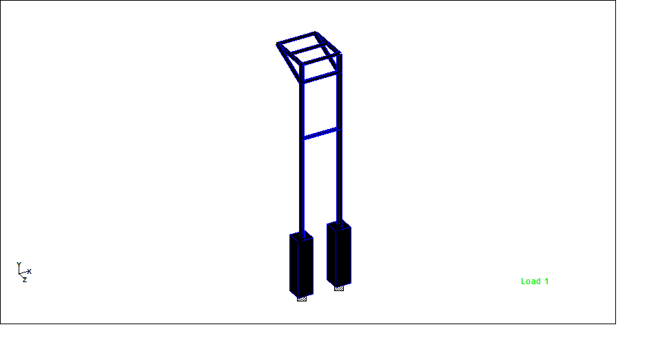
Hello friends, Welcome to Design and Think World .Today, I am discussing Cable Post Supporting Structure Design.
Purpose: – It is mainly used in 11/33 kV Distribution project as an overhead supporting arrangement for Cable.
Location Selection: –To be determined by the density of existing services, likely disruption to traffic and space requirements for construction of cable post.
Dimension: – Height =Normally 4.5 to 5 meter from FGL (assume ) ,Top Platform Size = 1meter *1 meter (assume)
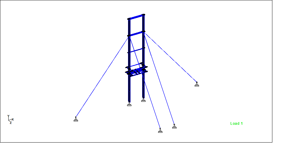
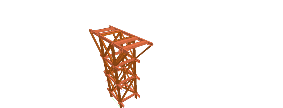
STAAD MODEL :- STEEL/CONCRETE both
CODAL PROVISION: – Structural steel shall be designed in accordance with the ‘General Construction in steel Code of Practice (IS 800 LSD) & Concrete shall be designed in Concrete code of practice (IS 456:2000).
Hello friends, Welcome to Design and Think World .Today, I am discussing RCC baffle wall /Fire Wall. It is usually used either Brick type or RCC Type depending upon Project Requirement
Purpose: – It is mainly used in Substation for purpose of limiting the damage and potential spread of fire from a transformer failure.
Dimension: – The Dimension of baffle wall may depends upon Site and Project requirement: (i) The Single Transformer Separation 132 & 220 KV: – 6 meter Length & 4.5 to 5.5 meter Height from GL Level. (Assume)
The design of RCC Wall divide into Four section :- (I) Design of Plate (ii) Design of Column (iii) Design of Beam
STAAD MODEL :- PLATE /Beam /Column Combined
CODAL PROVISION: – Concrete shall be designed in Concrete code of practice (IS 456:2000).
Hello friends, Welcome to Design and Think World .Today, I am discussing RCC Joint Bay with Link box Chamber. The Joint bay may either Brick type or RCC Type.
Purpose: – It is mainly used in EHV Underground Cabling Project for outer protection of Cable joints.
Location Selection: – For underground cable projects the joint bay location is selected in order to maximize each section length of cable. The size of the joint bay will be determined by the density of existing services, likely disruption to traffic and space requirements for cable drums and cable pulling equipment. Therefore, are normally located within or adjacent to public roads.
Dimension: – The Dimension of Joint Bay may depends upon Site and Project requirement: (i) The Single circuit 220 KV Cable =10 meter length & Width =1.5 to 2 meter for Staggered form joints. (Assume)
(ii)The double Circuit 220 KV Cable: – 16 meter Length & 2.5 meter for staggered form joints. (Assume)
The design of RCC joint bay divide into Four section :- (I) Design of Wall (ii) Design of Raft (iii) Design of Haunch (iv) The design of cover slab may or may not be used . It is depend upon site and Project requirement.
STAAD MODEL :- PLATE DESIGN
CODAL PROVISION: – Concrete shall be designed in Concrete code of practice (IS 456:2000).
PANEL SUPPORTING STRUCUTRE, TRANSFORMER SUPPORTING STRUCUTRE, HG FUGE SUPPORTING STRUCUTRE, T CONNECTOR SUPPORTING STRUCUTRE ALONG WITH PCC POLE DESINGED IN STAAD WHICH IS USED IN ELECTRICAL DISTRICBUTION PROJECT.
Note :-
In Steel and concrete fixing arrangement in Pole, I used concrete Between PCC pole and Steel for load and moment Transformer.
Cable wire provide additional support to PCC pole
Mainly Pinned support used in this design
Release moment Mx & Mz direction
Structural steel shall be designed in accordance with the ‘General Construction in steel Code of Practice (IS 800 LSD) & Concrete shall be designed in Concrete code of practice (IS 456:2000).
Basic Design principles: – Structural Concrete shall be designed in accordance with the ‘General Construction in concrete Code of Practice (IS 456 2000 )
BASIC LOAD CALCULATIONS
BASIC LOAD CALCULATIONS
SEISMIC LOAD: – IS 1893(part 1):2002
Zone
Factor: – 0.16
Importance factor: – 1.5
Response reduction Factor: – 5
DEAD LOAD: – (i) Terrace Slab (ii) Parapet
Wall load (iii) Self weight
Live Load: – Transformer Load: – 8 Ton
Load Combination
1.5 D.L. + 1.5 LL.
1.2 D.L. + 1.2 LL+ 1.2 EQX
1.5 D.L. + 1.2 LL+ 1.2 EQZ
Other Loading Combination on the Basic of Static Load Analysis